|
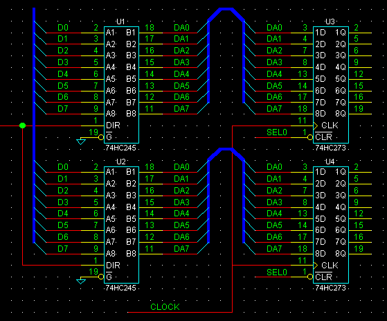
As for 2 to 8 pins of U1 and U2, each pin is connected by the network name of D0 to D7.
|
|
Since "1" pin of U1 and "1" of U2 connect with the wire, they are connected in one network.
|
|
19 pins of U1 and U2 are connected to GND.
|
|
As for "1" pin of U3, and "1" of U4, a signal name is connected as a network of "SEL0."
|
|
Although "10" of U1, U2, U3, and U4 is not displayed, a non-displaying power-supply pin is connected to the network of GND.
|
|
"20" pins are similarly connected to the network of VCC.
|
|
Since it does not connect at a junction, 11 pins of U4 are not connected to network name CLOCK.
|
|
Although the bus of 18 to 11 pins of U1 and 3 to 18 pins of U3, 18 to 11 pins of U2, and 3 to 18 pins of U4 have separated by bus Since a signal name is the same, it connects with a network.
(In DA0, "18 of U1", "18 of U2", "3 of U3", and "3 of U4" become the same network.)
|
 The rule when attaching a signal name
 support@yansoft.com